2021-08-03
Last time we talked about component installation and pre-flight inspection. Now, before flying up, what we need to do is only Flight Planning.
Thanks to the continuous optimization from Kolida engineers, flight planning of Kolida H700 is easier than the models before, mainly there are three parts only: Defining Mission Area, Generating Flight Route, Setting Route Parameters.
1. Defining Mission Area
1.1 Mission Area Positioning
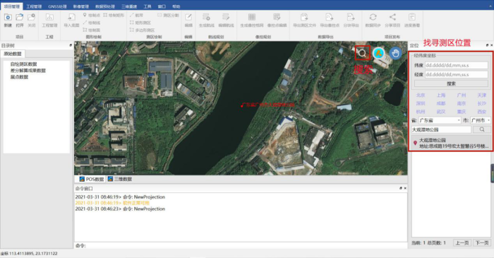
Run KolidaUAV Aerial Survey Integrated Platform, a PC software, input the location of the mission area.
1.2 Create Project
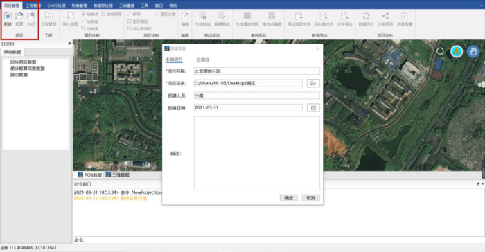
Find the Project Management menu, select New, input the project name and saving path, and click OK to create the project.
1.3 Defining Mission Area
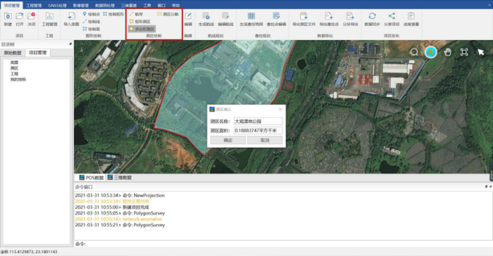
Find the Mission Area Drawing toolbar.
1.3.1 Mission Area with Block Shape
There are two options: Rectangular Mission Area or Polygon Mission Area. Choose the suitable one, draw the mission area range line on the map, then input the mission area name.
1.3.2 Mission Area with Ribbon Shape
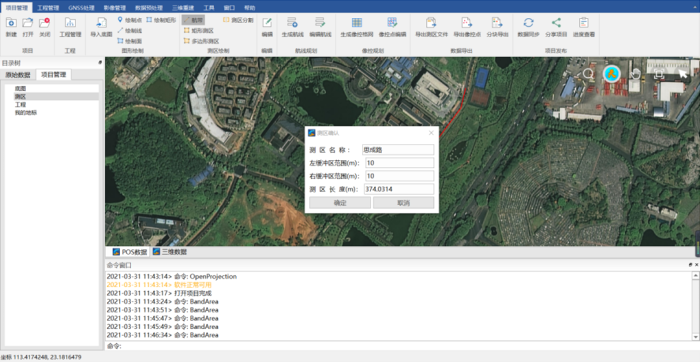
Choose “Flight Strip”, draw mission area range line on the map, then input mission area name and the extension width of the flight route.
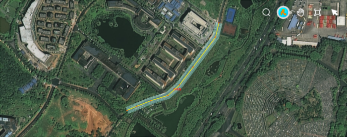
1.4 Generate KML
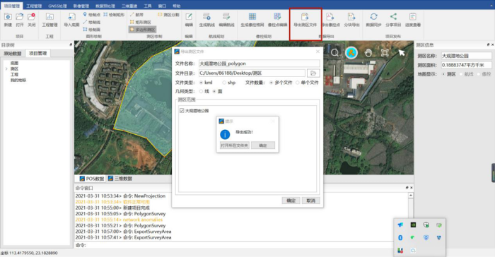
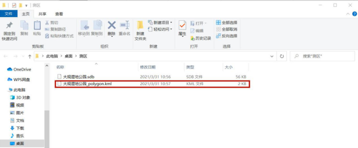
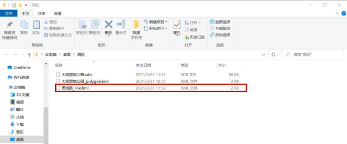
Find the Data Export toolbar, click “Export Mission Area File”, select the saving path, file type and number of files. For mission area in block shape, we choose “Surface”, for mission area in ribbon shape, we choose “Line”.
2. Generating Flight Route
2.1 Connect to PC
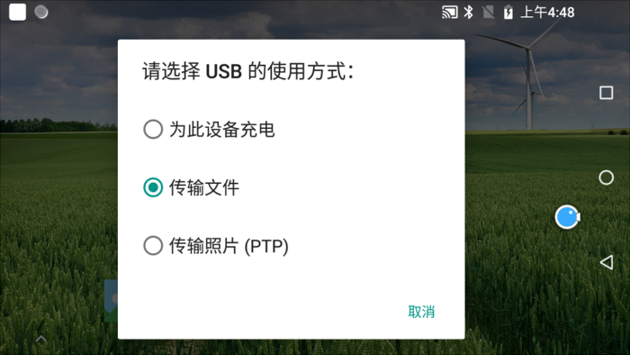
Connect the remote controller with PC via a Type-C cable, choose USB mode “Data Transfer”.
2.2 Copy the .kml file to Controller
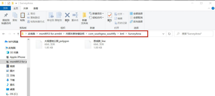
Copy the .kml file to controller memory space, at:
internal storage>com_southgnss_southfly>kml>SurveyArea floder.
2.3 Connect to wifi
Connect the remote controller to wifi internet, because Internet connection is needed for pre-work inspection, map loading and terrain imitating functions)
2.4 Route Planning
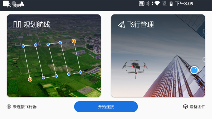
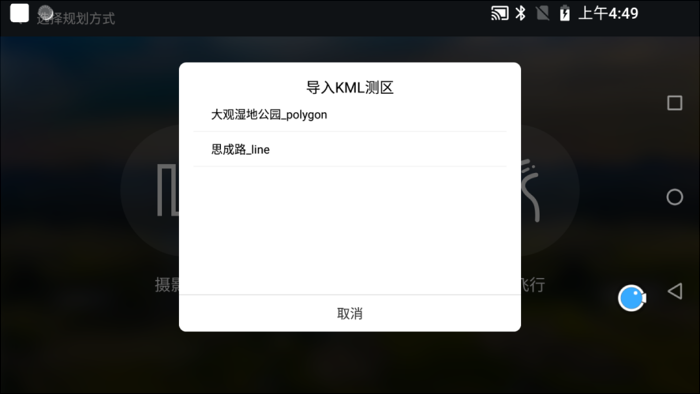
Run Ground Control Station software, click “Route Planning”, setting parameters, the ground station automatically plans the route.
3. Setting Route Parameter
3.1 Flight Altitude and Speed Setting:
The flight altitude is determined according to the project requirements and flight safety requirements. Commonly we set the flight speed to 8m/s.
3.2 Overlap Rate Setting
Generally we set the heading overlap rate to 80%, and the side overlap rate to 75%.
3.3 Camera Setting
When we use single-lens camera we choose S24.
When we use five-lens camera we choose T53.
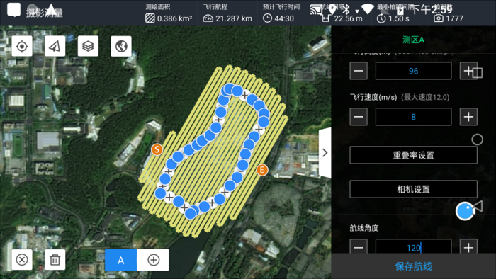
3.4 Setting Rotation Angle of the Route (120° in this case)
Set the rotation angle of the route according to the trend of the mission area. The route should turn as less as possible. (The photo quality is low when the drone is turning, and the turning greatly consumes power).
Check the position of the start point (Start S) and the return point (End E), the return point(go-home point)should be close to the take-off point. If the returning distance is short, the power consumption will be less and the flight will be safer.
3.5 Route Expanding (96m in this case)
If the mission is 3D modeling, using an oblique camera. The expanding value we input should be the same with flight altitude.
If the mission is to collect orthophotos, no need to set Expanding value.
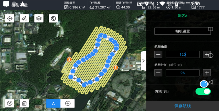
3.6 Save the Route
Before saving, review and confirm the parameters and name the route. Usually we input the mission area name + flight altitude, click “confirm” to complete.
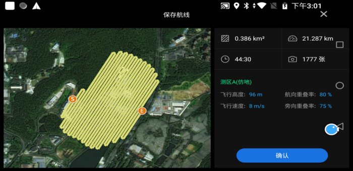
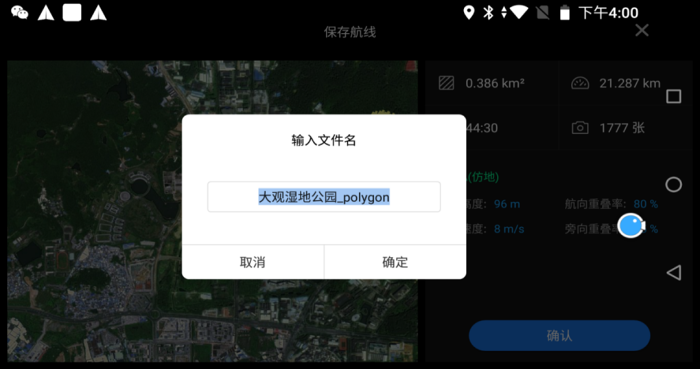
Now all settings are done.