


2026-09-07
In surveying and CAD drafting workflows utilizing laser scanners, engineers often overlay X-ray Orthophotos as geometric snapping basemaps (to draft wall lines) alongside standard Orthophotos (to reference materials and colors). This combination maximizes both efficiency and accuracy.
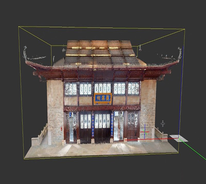
While Orthophotos and X-ray Orthophotos share the exact same source data, their underlying algorithms, point cloud projection rules, and rendering logics differ significantly. In short: point-cloud-based Orthophotos present only top-surface point data, whereas X-ray Orthophotos penetrate through the entire point cloud along the projection direction to map point density distribution.
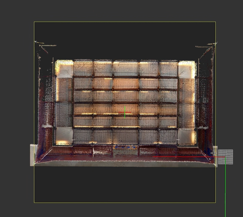
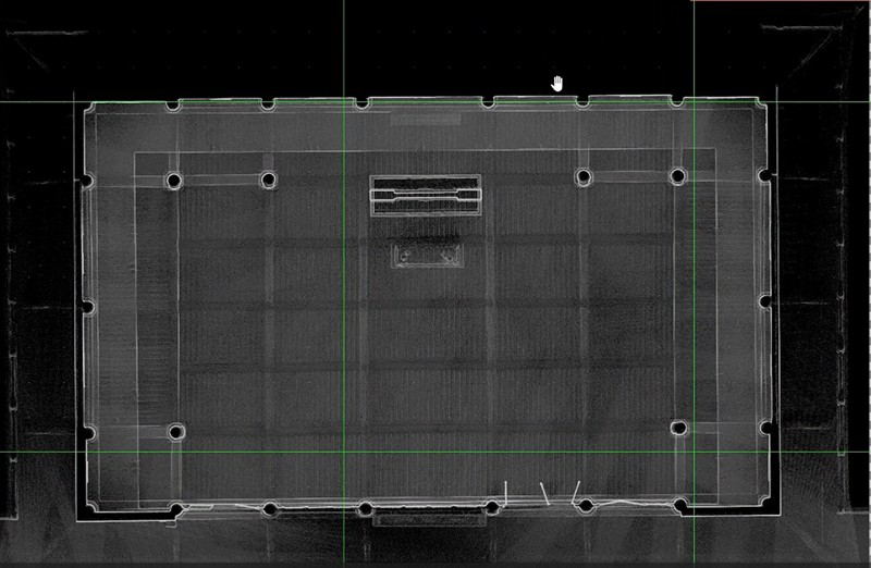
Projection Rule (Selects a Single Point): The algorithm casts rays downward from directly above (top-down view). During rasterization/gridded processing, each (x,y) pixel grid retains only the highest point or the point closest to the camera (typically using highest point projection, Zmax.
Rendering Logic: Maps the selected point's RGB color or laser reflection intensity.
Visual Effect: Displays top-layer surface geometry, acting like an "umbrella" (e.g., roofs, tree canopies, ground surfaces), while fully obscuring walls and ground underneath the roofs. Visual information consists of surface true color (RGB) or laser reflection intensity.
Vector Line Characteristics: Wall edges blur together with eaves and roof edges, making boundary definitions fuzzy.
Projection Rule (Penetrates and Accumulates All Points): The algorithm penetrates through the full depth of the point cloud along the projection direction (e.g., top-to-bottom), counting the total number or intensity of points passing through each pixel grid (Point Density / Intensity Accumulation).
Rendering Logic: Uses a designated color gradient map (such as a black-white-grayscale palette, where higher point counts appear brighter or darker) to visualize point density distribution.
Visual Effect: Delivers an "X-ray perspective" look. Flat roofs or ground surfaces feature low vertical point density (as points form only a single layer) and appear dark or transparent. Conversely, vertical walls, columns, and vertical shafts overlap and accumulate vertically within a minimal (x,y) area, resulting in high point density. They render as crisp, bright lines that highlight the structural skeleton.
Vector Line Characteristics: Intersections of walls and columns form razor-sharp, high-contrast, highlighted vector lines.
Solves the Wall-Corner Snapping Dilemma in CAD: X-ray Orthophotos effectively "evaporate" roofs, exposing highlighted intersection lines formed by vertical walls beneath. Operators in CAD can snap directly to true wall corners and wall lines with millimeter-level accuracy, increasing tracing efficiency by 5 to 10 times.
"See-Through" Visibility for Indoor and Multi-Story Structures: X-ray orthophotos penetrate roofs and ceilings, presenting clear views of load-bearing walls, partition walls, column grids, and outer outlines of heavy equipment—functioning as a geo-referenced, panoramic plan/section basemap.
Data Lightweighting: Delivering 2D Images Instead of Heavy 3D Point Clouds: Processing massive 3D point clouds spanning hundreds of GBs places heavy demands on client hardware, and non-surveying professionals often struggle to slice and navigate 3D point clouds. Exporting a high-resolution X-ray orthophoto (GeoTIFF/JPG) yields a file size of only a few dozen MBs while fully preserving the entire 3D point cloud's geometric skeleton. Clients can drag this image directly into AutoCAD or GIS software to use as a precision basemap.
Generating an Orthophoto from laser point clouds acts like "surface photography"—telling you what the surface looks like (Color & Surface).
An X-ray Orthophoto provides "skeletal perspective"—telling you where vertical structures are located (Structure & Density).
The Rebuild3D plugin built into AcuteLAS Studio 2026 supports generating both standard Orthophotos and X-ray Orthophotos. Check out the video below for step-by-step instructions.
videos : https://www.youtube.com/watch?v=GyiuXZO4JwU




KOLIDA Instrument (KOLIDA) is a leading manufacturer of precision surveying equipment.
COMPANY PROFILE