2022-04-02
To level up a total station from 2 second accuracy to 1 second, what production processes shall we go through? Let's see the six significant improvements on producing skill and fourteen high standard inspection steps.
1. Continuously Innovating Hardware design
1.1 Vertical axis (from Half-Movement style to Concentrated-Ball Style)
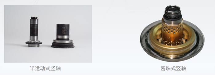
A. The inner and outer shafts and the steel ball are in interference fit, to make sure that there is no-gap rotation, and no accuracy loss within the range of -40°C to +60°C.
B. More than 100 high-precision steel balls are arranged on the cylindrical cage, and the rotation track of each steel ball does not overlap. It can be considered that the rotation center of the inner shaft is the average value of the revolution centers of the 100 steel balls, which make the rotation axis more accurate.
C. There is only rolling friction, and no sliding friction in vertical axis. The vertical axis is not easy to jam, and the rotation is smoother than before.
1.2 Horizontal axis (from Split Style to One-piece Style)

The horizontal axis has one-piece structure, which eliminates the minor non-coaxiality produced by the non-concentric from the last generation segmented combined structure. It eliminates the poor angular accuracy generated during the rotation. This structure increased the machining accuracy and the success rate of one-time machining.
1.3 A New Tangent Screw Structure (Smaller Thread Spacing Reduces 50% Collimation Error)
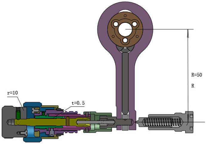
The sensitivity of human hand usually is 0.1-0.2mm, equal to about 0.5 degree of the handwheel.
When the screw pitch is 0.5 mm, the handwheel rotates 0.5 degree, and meanwhile the instrument rotates for 2.8 seconds.
When the screw pitch is 0.25 mm, the handwheel rotates 0.5 degree, and meanwhile the instrument rotates for 1.4 seconds.
For a manual total station, a large part of the measurement accuracy of the instrument depends on the collimation accuracy. By optimizing the tangent screw structure of the instrument and reducing the thread spacing, we can effectively improve the machining accuracy of parts, and help users to aim at the target more precisely, reduce the error.
1.4 Compensator is Relocated and Redesigned

A. The compensator for 1” total station has been relocated from bottom part to the upper part of the vertical axis to minimize the influence of centrifugal force caused by the rotation of the instrument, to guarantee the stability during instrument operation.
B. The reflective lens has been redesigned to increase light transmittance and reduce noise interference. As a result, the error can be reduced to one-sixth of the last generation. Within the temperature range from -20℃ to 50℃, the performance reached the same level of international Known brands.
C. Special adjustment has been arranged for each single compensator, more procedures and parameters has been added to increase the quality control points of the adjustment and make sure that the accuracy of each compensator is consistent.
1.5 A Dedicated Encoding Disc and Algorithm to Improve Angle Accuracy
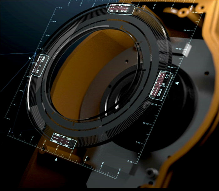
A. A dedicated high-precision absolute encoding disc has been used in 1” total stations. The increased encoder accuracy promotes a leap in the total station's angle measurement accuracy.
B. Quadruple CCD probe detecting method and optimized angle measurement algorithm is onboard.
1.6 Ranging Accuracy Improved by 6 Measuring Tapes and 150 Mhz Phase Solution
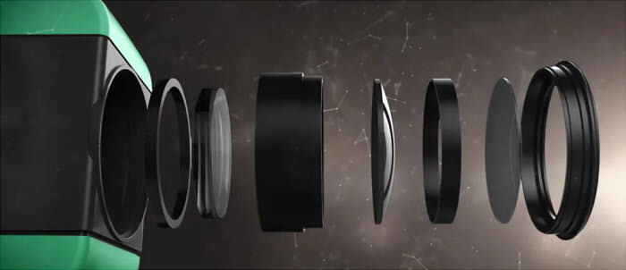
A. 150 MHz ultra high-frequency phase solution has been used for distance measuring, which used a high-precision crystal oscillator to prevent the distance measurement result from being affected by temperature. It makes sure the distance measuring accuracy is stable in harsh environments.
B. 6 measuring tapes work simultaneously for the distance calculation, to improve the accuracy and reliability.
The reflective lens groups have been reorganized to reduce the crosstalk of stray light.
2. Inspection Process: 14 Main Steps to Make Out a Reassuring Instrument
2.1 Ultrasonic Cleaning
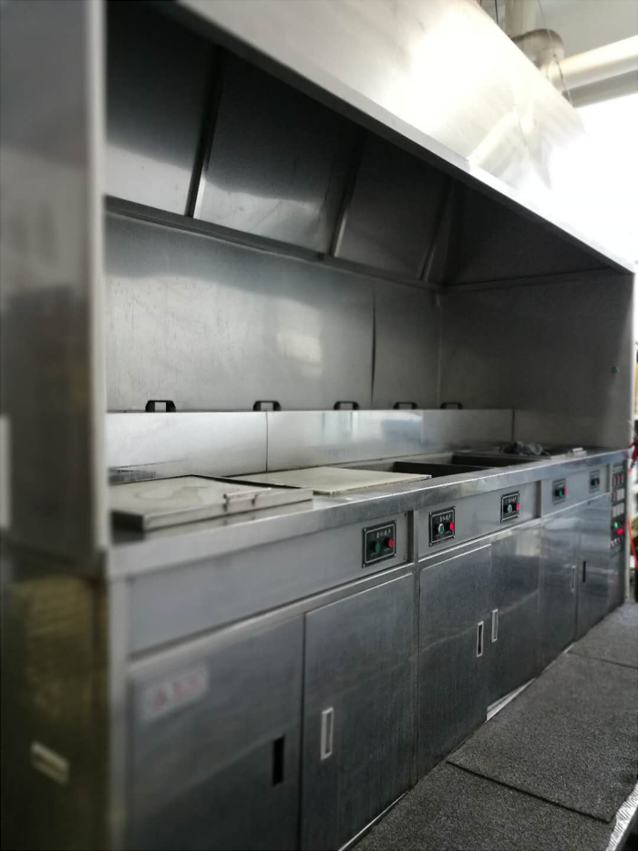
The metal parts processed from the metalworking workshop will be ultrasonically cleaned here. What inside the first pool is special metal cleaning agent, the second is clean water, and in the third pool is also clean water. All parts must be cleaned in these three tanks for totally 15 minutes. After cleaning, parts will be directly stored in the warehouse.
2.2 Laser Marking
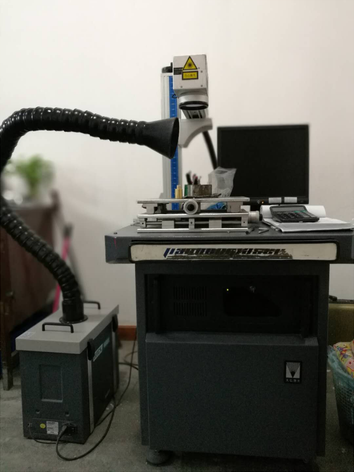
In order to ensure the production accuracy of the instrument, some metal parts are dedicated to be used for a certain total station. So we number every part by laser to track it, to ensure the quality of each part.
2.3 Hardness Testing
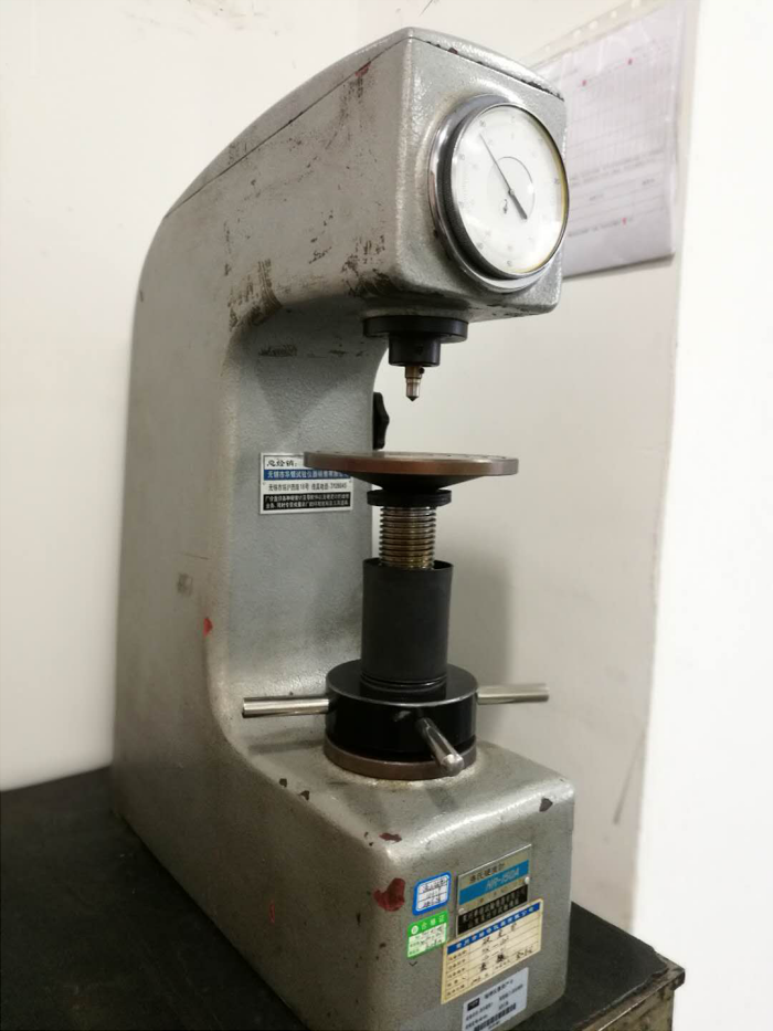
We use Automatic Turret Micro Rockwell Hardness Tester to detect whether the metal surface hardness meets the requirements of R&D.
2.4 Roughness Testing
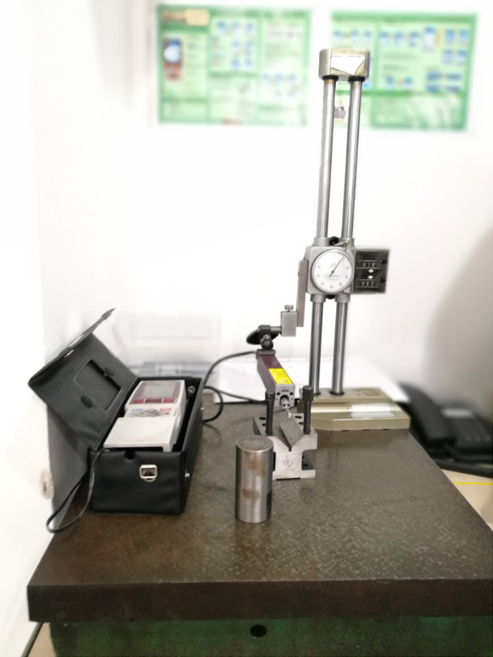
We use DC resistance tester to detect the roughness of the metal surface.
2.5 Keypad Life Testing
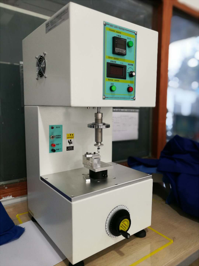
We use Keystroke Life Tester, set the hit number to 100,000 times, and then test whether the keys can always survive.
2.6 Battery Testing
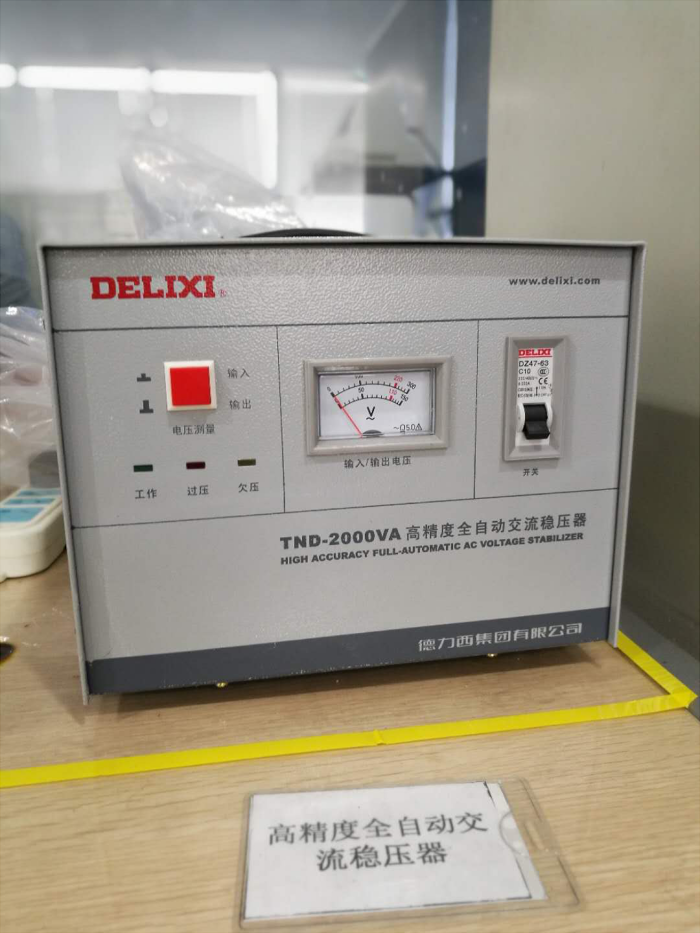
We use High-precision automatic AC voltage stabilizer, set a certain current and voltage, to test the charging and discharging time of the battery.
2.7 2D Scanning
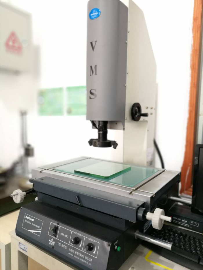
We use VMS image measuring instrument to carry out two-dimensional scanning of spare parts, to match and proofread with the research and development design drawings.
2.8 3D Scanning
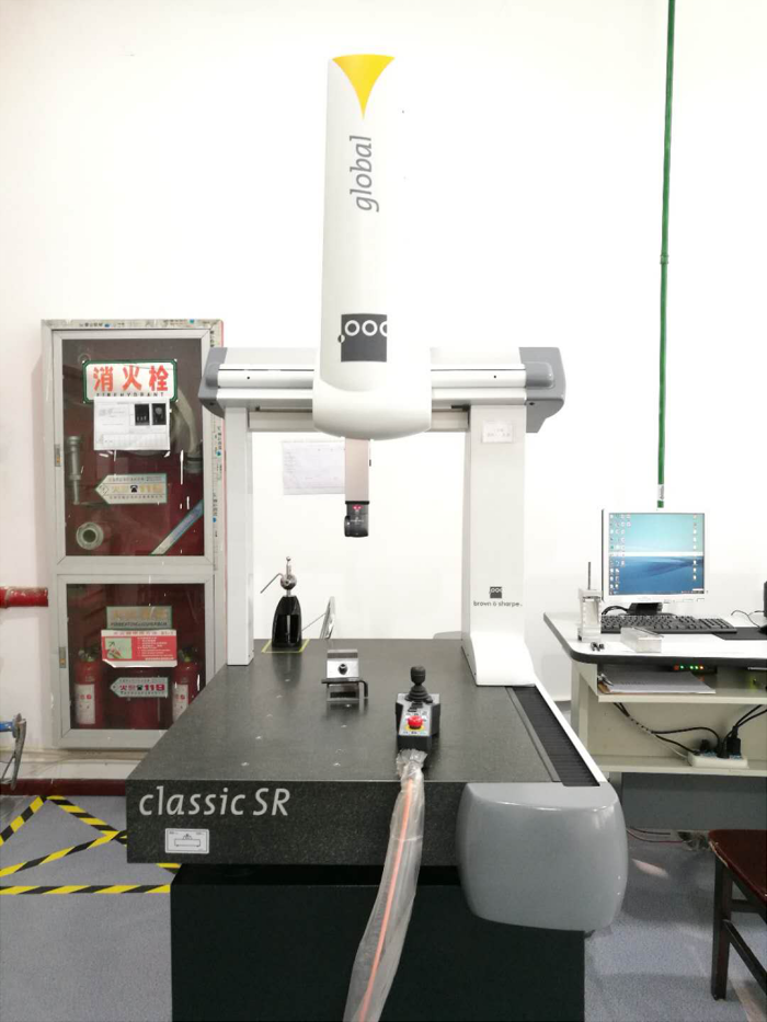
We use a Three-coordinate scanner to to perform three-dimensional scanning of parts to detect coaxiality, symmetry, perpendicularity, concentricity, etc.
2.9 Air Tightness Testing
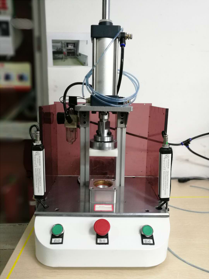
We need to make Air Tightness Testing for both of complete instrument and some parts, to ensure the waterproof and dustproof capability of the instrument.
2.10 High and Low Temperature
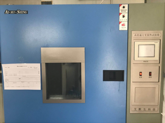
We use Alternating Damp Heat Test Chamber to test instrument with extreme high and low temperature, to ensure that the instrument maintains the consistency of accuracy whether it is hot summer or cold winter.
2.11 0.2” Accuracy Testing
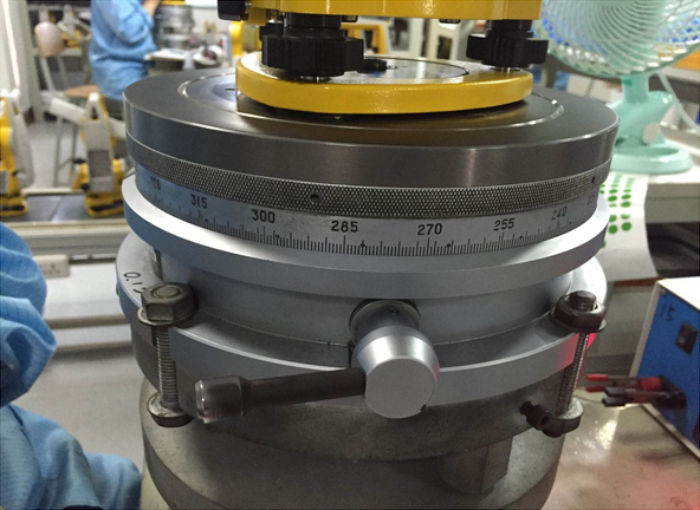
We use a Multi-tooth Indexing Table to finally determine whether the angle accuracy of a total station meets the 1 second standard. The testing accuracy must reach as high as 0.2". The reliability can be guaranteed only when the accuracy we get in laboratory test is higher than the standard requires.
2.12 Concentricity, Coaxiality, Roundness Testing
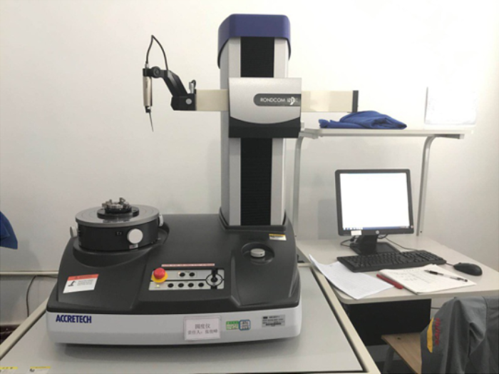
We use a Roundness Meter for its extremely high angular accuracy to guarantee accurate measurement of concentricity, coaxiality, and arc roundness of our precision parts.
2.13 Vibration Testing
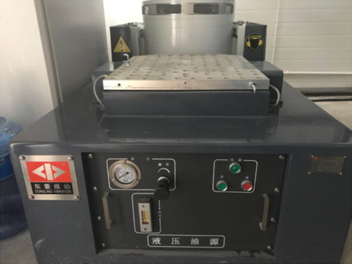
In order to test the stability of the instrument structure and make sure that it would not be damaged by the international transportation of air and sea, each instrument will be subjected to a high-intensity vibration test before leaving the factory.
2.14 Making a Complete Report
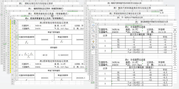
After all the inspection procedures are completed, we make a test report for each instrument and record it. It will be used for future service and customer care.
Video: a factory tour to Kolida Changzhou Factory
Video: Assembly and final test of 0.3mm Digital Level, Kolida,Professional Survey Equipment Manufacturer
Video: Changzhou factory tour, Kolida, Professional Survey Equipment Manufacturer
See the Datasheets from:
Google Drive: https://drive.google.com/file/d/1QLfWt2X1FucWh5jsjqJhTaUdzhi2nTmt/view
Google Drive: https://drive.google.com/file/d/1QrX3_XlenyMjggBz_NkE26lTnSVft5Vj/view